
A real-world investigation into excessive HPT blade scrap rates that revealed cooling flow starvation, hot gas ingestion, and the need for a targeted design upgrade.
Operators of an industrial aeroderivative gas turbine experienced unexpectedly high scrap rates of high-pressure turbine blades, driving increased costs and shortened overhaul intervals. Liburdi investigated the failure mechanism and identified oxidation driven by internal cooling design limitations.
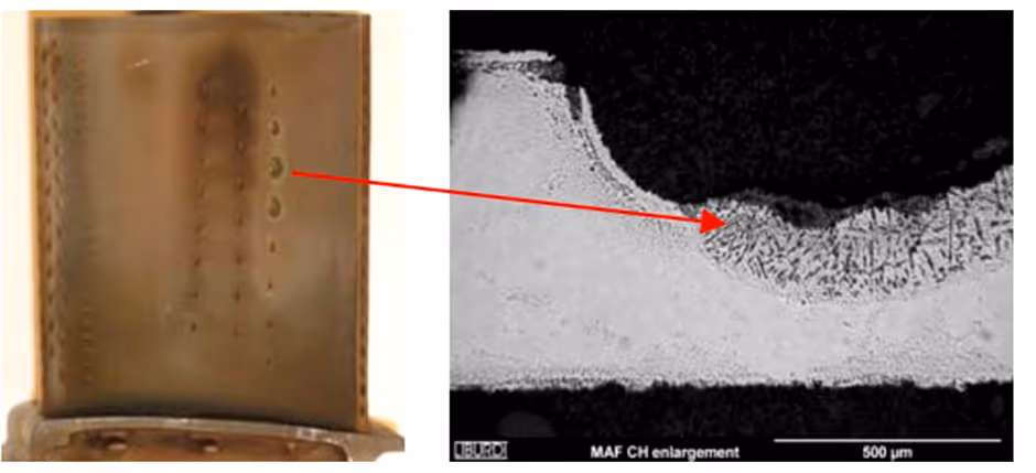
The oxidation attack generated a significant loss of thickness and base material, shown in Figure 1, limiting part life and impacting the gas turbine engine overhaul interval. These findings highlight the importance of effective gas turbine blade repair in mitigating oxidation-related damage and extending service life.
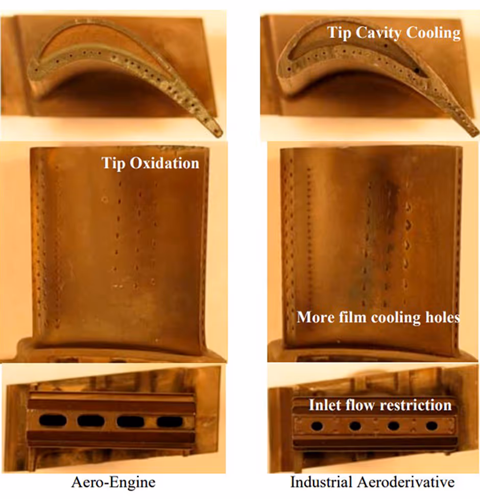
A detailed comparison between the industrial aeroderivative high pressure turbine blade and its aeroengine version identified differences. The aeroderivative turbine blade has two tip cavity holes and more film cooling holes on the pressure side of the airfoil. The inclusion of a metering plate on the aeroderivative cooling air inlet (Figure 2) shows the differences.
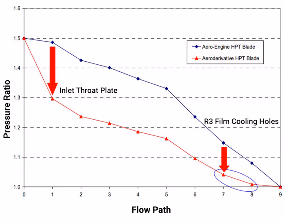
Using the aeroengine configuration as a baseline, Liburdi developed a compressible flow network analysis (CFNA) model to understand the turbine blade's internal air flow rate, flow distribution, and pressure drop along the flow path.
The CFNA model predicted a significant pressure drop across the metering plate of the aeroderivative design compared to the aeroengine design shown in Figure 3. The low internal pressure difference across the row 3 film cooling holes on the pressure side of the airfoil could become zero. This could cause no flow (cooling hole starving), or even negative air flow, resulting in flow reversal (hot gas ingestion) during transient or off-design conditions.
In the laboratory, dimensional and airflow rig testing confirmed suspicions; The inlet metering plate combined with a large total exit flow area of the aeroderivative high pressure turbine blade design reduced cooling flow, altered internal flow pattern, and reduced internal pressure.
Liburdi concluded that hot gas ingestion during off-design or transient conditions could cause oxidation of the HPT blade row 3 film cooling holes. As mitigation, Liburdi recommended upgrading the design to introduce more cooling flow to the trailing edge circuit and reduce the risk of hot gas ingestion. Liburdi's complete analysis included a review of the impact of additional cooling air extraction on the other components in the Aeroderivative engine. This work supports operators seeking to improve reliability and part longevity through advanced gas turbine blade repair solutions.
You can read the complete study in the ASME Turbo Expo paper GT2008-50431.
To see how Liburdi can save you money by maximizing your equipments operation and extending the life of your parts, contact us at info@liburditurbineservices.com.